FNIC drain-type fluid couplings for IC engines
Drain-nozzle couplings purpose-built for internal-combustion engine drives — engine-mounted, self-contained and ready for continuous clutching and declutching at the flick of a valve.
A coupling that lives on the engine.
Fluidomat FNIC are drain-nozzle type fluid couplings designed specifically for combustion-engine drives. Where a diesel or gas engine powers a working machine, the FNIC takes the place of a conventional clutch — letting the engine start and idle on no load, then engage smoothly and disengage at will while it keeps running.
The unit is supplied complete with its own oil circuit and controls, so it bolts straight onto the engine and connects to the driven machine without a separate hydraulic pack. It absorbs shock loads, dampens torsional vibration and protects belt drives from slip — all the proven benefits of fluid coupling, packaged for mobile and engine-driven plant.
Key data
Built around the engine driveline
The coupling mounts on the engine SAE flange through its stationary housing and connects to the engine flywheel by an elastic coupling on the input shaft. The output end can be connected to the driven machine by a pulley, an elastic coupling or a cardan shaft to suit the installation.
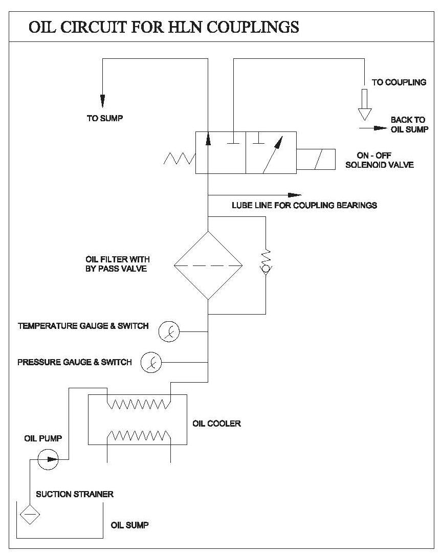
An integrated oil-feeding pump, driven by the IC engine, supplies the working circuit. A solenoid valve switches the oil flow either into the working circuit or back to the oil sump as a bypass, while an oil filter keeps the circuit clean and leak-off nozzles on the coupling periphery continuously drain hot oil from the working circuit.
Standard accessories supplied
- Engine-driven oil pump
- Oil filter
- Solenoid valve
- Flexible coupling on input shaft
- Oil temperature and pressure switch
- Oil level indicator
Clutch and declutch with one valve
During power transmission — the clutching mode — oil flows into the working circuit through the oil cooler, filter and solenoid valve. Hot oil from the working circuit leaks off continuously through the nozzles and returns to the oil sump, so the coupling runs cool while it transmits power to the driven machine.
For declutching, the solenoid valve simply bypasses the circulating oil — after the cooler and filter — straight back to the sump instead of into the working circuit. The residual oil in the working circuit empties through the leak-off nozzles and power transmission stops while the engine keeps running. Switching the valve again re-engages the drive, giving continuous clutching and declutching without touching the engine.
Why FNIC for engine drives
No-load start-up of the engine in declutch mode, continuous clutching and declutching by switching the solenoid valve, absorption of shock loads and torsional vibration, smooth start-up of the driven machine, belt slippage avoided in belt drives, rugged construction with high radial-load capacity and easy maintenance.
Rating table — FNIC combustion engine drive
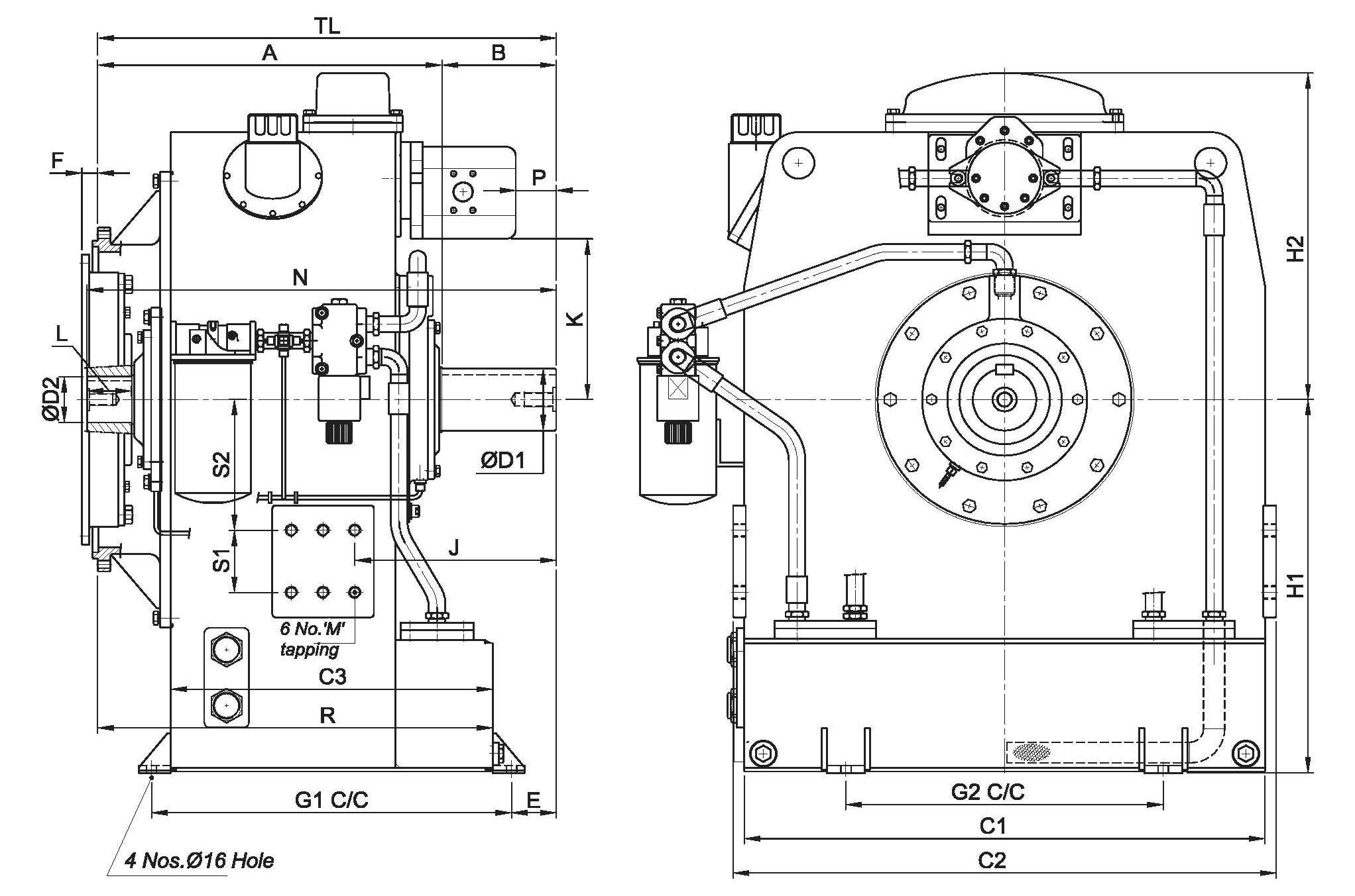
Mounting and overall dimensions by frame size and SAE / flywheel interface. For final selection and the full dimension tables, please consult Fluidomat application engineering.
| FNIC | SAE & flywheel | F (mm) | A (mm) | B (mm) | TL (mm) | R (mm) | Dry wt. (kg) |
|---|---|---|---|---|---|---|---|
| 500 | SAE-1; 14" | 25.4 | 455 | 150 | 605 | 458 | 498 |
| 540 | SAE-1; 14" | 25.4 | 542 | 180 | 722 | 622 | 655 |
| 540 | SAE-0; 18" | 15.7 | 551 | 180 | 733 | 631 | 667 |
| 615 | SAE-1; 14" | 25.4 | 620 | 180 | 800 | 705 | 846 |
| 615 | SAE-0; 18" | 15.7 | 629 | 180 | 809 | 714 | 864 |
SAE-0 / 18" flywheel interfaces are also available for the 540 and 615 frames. Full dimension data and the oil circuit are given in the sections below.
FNIC dimension table
Overall and mounting dimensions (mm), oil quantity and mass moment of inertia (‘J’ value) by frame size.
| Model FNIC | H1 | H2 | ØD1 | ØD2 | L | S1 | S2 | M | J | E | C1 | C2 | C3 | G1 | G2 | N | K | P | Oil Quantity in litres | 'J' Value with Oil in kg·m² |
|---|---|---|---|---|---|---|---|---|---|---|---|---|---|---|---|---|---|---|---|---|
| 500 | 500 | 486 | 80 | 65 | 68 | 100 | 170 | 16 | 264 | 118 | 700 | 736 | 361 | 421 | 450 | 623 | 281 | 42 | 36.0 | 4.08 |
| 540 | 600 | 525 | 100 | 74 | 70 | 100 | 210 | 20 | 317 | 70 | 820 | 855 | 507 | 567 | 500 | 739 | 305 | 64 | 72.0 | 5.06 |
| 615 | 600 | 635 | 100 | 90 | 80 | 100 | 250 | 20 | 320 | 65 | 830 | 800 | 569 | 629 | 530 | 816 | 362 | 74 | 80.0 | 7.76 |
All dimensions in mm. ‘J’ value = mass moment of inertia with oil (kg·m²).
Oil circuit & construction
An engine-driven oil pump feeds the working circuit through cooler, filter and solenoid valve; leak-off nozzles empty the circuit for declutching.
Made for engine-driven plant
Driving a machine off an engine?
Tell us your engine, flywheel and SAE flange details and we'll specify the right FNIC coupling for your drive.