Type HF / HFD / HF-DX
Radially displaceable couplings — easy fitting and removal, outer-wheel brake-drum option.
Constant-fill, fixed-speed couplings built for easy alignment.
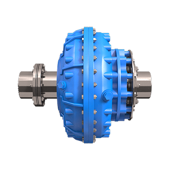
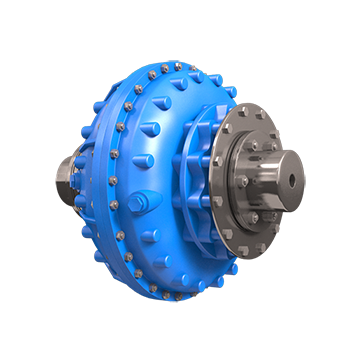
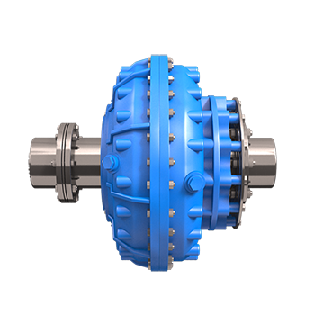
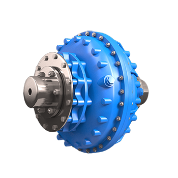
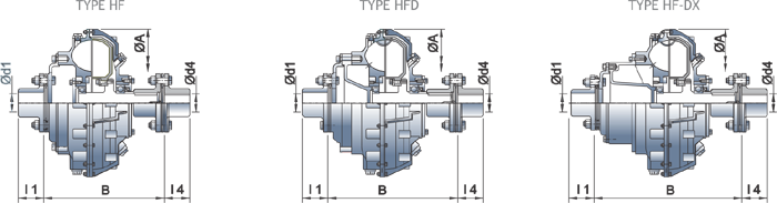
The Fluidomat Type HF range is a constant-fill (fixed-speed) fluid coupling that is radially displaceable — driving and driven shafts can be pre-aligned, and the coupling fitted or removed, without disturbing either machine. A metallic disc flexible coupling is provided on both the input and output sides.
To match the starting and running characteristics of industrial machines, Fluidomat offers three circuit types that deliver starting torque down to 120% of nominal torque. Type HF is the basic coupling without a delay-fill chamber; Type HFD adds a delay-fill chamber; and Type HF-DX uses an extended delay-fill chamber for the lowest starting torque. All offer normal operating slip of 2–5% depending on size and torque setting.
Key data
Three circuit types, one rugged platform
Choose the circuit that matches your machine's starting duty — each is built on the same radially displaceable construction.
- Type HF (basic, no delay-fill chamber): starting torque adjustable from 180% to 275% of nominal
- Type HFD (delay-fill chamber): starting torque adjustable from 150% to 275%
- Type HF-DX (extended delay-fill chamber): starting torque adjustable from 120% to 270%
- Normal operating slip of 2% to 5%, depending on coupling size and starting torque value
- Fusible plug blow-off temperature of 130°C as standard; 160°C optional
- Suitable for two consecutive starts from hot and three from cold
- Radially displaceable design enables pre-alignment and easy fitting or removal
- Metallic disc flexible coupling on input and output; outer-wheel brake-drum mounting available
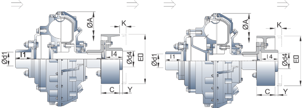
Brake-drum (outer-wheel drive) option. For braked drives, the HF range can be supplied with an outer-wheel brake-drum mounting. Because the coupling is radially displaceable, the brake drum is shifted by a defined dimension during removal — so ensure the machine or gearbox shaft length leaves adequate space for this shift.
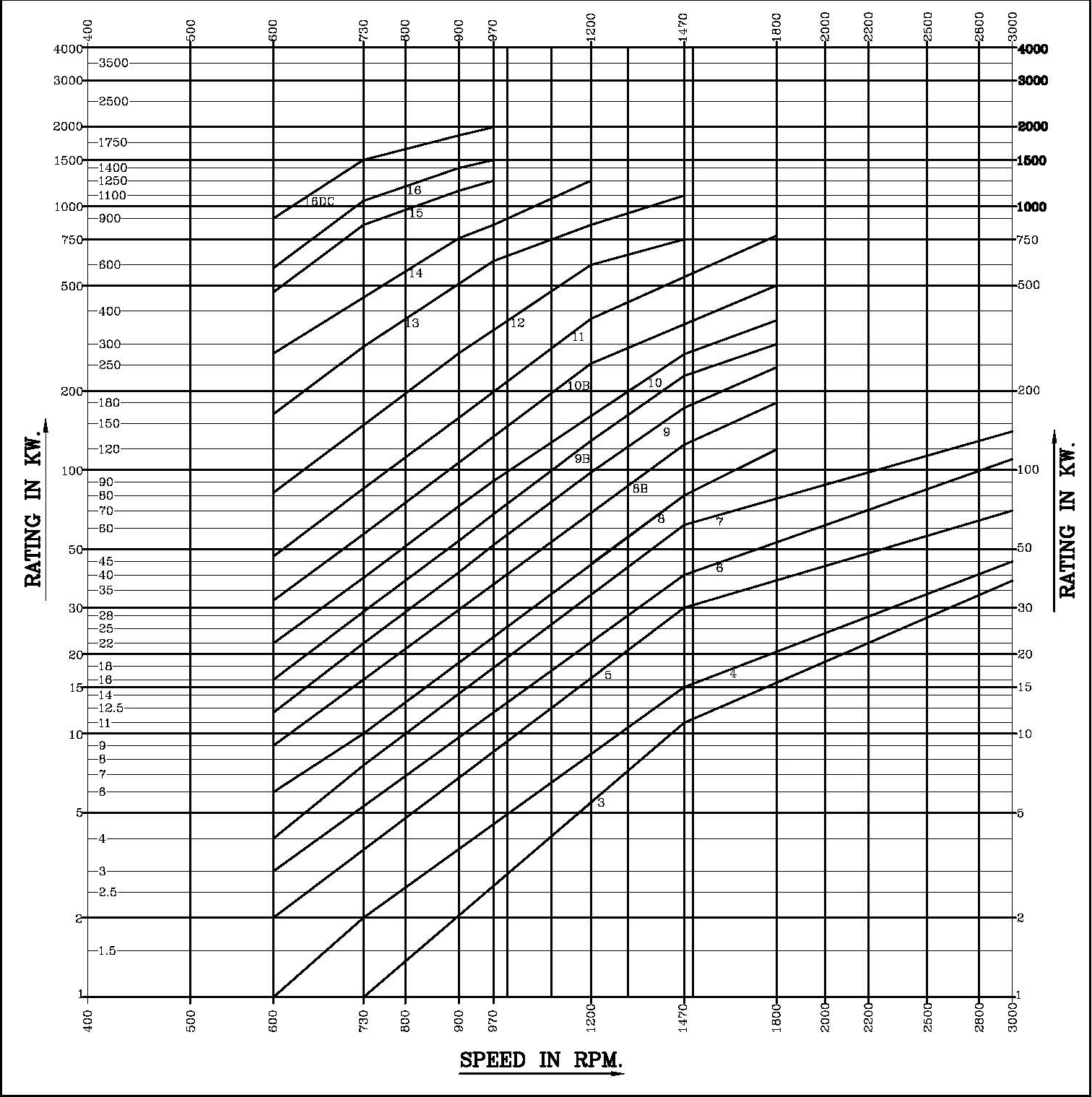
Rating table — HF / HFD / HF-DX
Maximum ratings in KW at different input speeds (RPM). For final selection, please consult Fluidomat application engineering.
| Model | 500 | 600 | 750 | 900 | 1000 | 1200 | 1500 | 1800 | 3000 | 3600 |
|---|---|---|---|---|---|---|---|---|---|---|
| 1 | — | — | 0.5 | 0.9 | 1.2 | 2.2 | 4 | 7.5 | 20 | 26 |
| 2 | — | — | 0.9 | 1.7 | 2.2 | 4.1 | 7.5 | 13.7 | 30 | 36 |
| 3 | — | — | 1.3 | 2.4 | 3 | 6 | 11 | 18 | 38 | 45 |
| 4 | — | 1 | 2 | 4 | 5 | 9 | 16.5 | 22 | 45 | — |
| 5 | — | 2 | 4 | 7 | 9 | 16.3 | 30 | 42 | 70 | — |
| 6 | — | 3 | 5 | 9 | 11 | 22 | 40 | 60 | 110 | — |
| 7 | — | 4 | 8 | 15 | 18 | 34 | 62 | 85 | 140 | — |
| 8 | — | 6 | 10 | 18 | 23 | 44 | 80 | 120 | — | — |
| 8B | 5 | 9 | 16 | 29 | 36 | 68 | 125 | 180 | — | — |
| 9 | 7 | 12 | 22 | 41 | 52 | 98 | 172 | 246 | — | — |
| 9B | 9 | 16 | 29 | 54 | 68 | 129 | 228 | 300 | — | — |
| 10 | 13 | 22 | 39 | 73 | 91 | 172 | 275 | 370 | — | — |
| 10B | 18 | 32 | 57 | 107 | 134 | 253 | 373 | 500 | — | — |
| 11 | 27 | 47 | 85 | 158 | 198 | 374 | 525 | 775 | — | — |
| 12 | 47 | 82 | 148 | 278 | 348 | 600 | 750 | 1000 | — | — |
| 13 | 95 | 163 | 293 | 550 | 620 | 850 | 1100 | — | — | — |
| 880 | 130 | 225 | 400 | 700 | 810 | 1150 | 1550 | — | — | — |
| 14 | 160 | 277 | 500 | 758 | 850 | 1250 | — | — | — | — |
| 15 | 275 | 472 | 850 | 1148 | 1250 | — | — | — | — | — |
| 16 | 340 | 583 | 1050 | 1400 | 1500 | — | — | — | — | — |
| 16DC | 520 | 900 | 1500 | 1862 | 2000 | — | — | — | — | — |
| 1330 | 720 | 1250 | 2450 | 2500 | — | — | — | — | — | — |
Couplings for 3000 RPM to be selected only after Fluidomat’s approval.
Technical specification & dimensions
Overall dimensions (mm), maximum bore, dry weight, oil filling and the connected metallic-disc flexible-coupling model, by frame size.
| Model HF | ØA | B — HF | B — HFD | B — HF-DX | Ød1 & Ød4 max | l1 & l4 | Dry wt HF * | Dry wt HFD * | Dry wt HF-DX * | Oil HF | Oil HFD | Oil HF-DX | Flexible coupling |
|---|---|---|---|---|---|---|---|---|---|---|---|---|---|
| 3 | 342 | 239 | 295 | 329 | 55 | 70 | 25 | 28 | 29 | 2.9 | 3.9 | 4.3 | FXC-I |
| 4 | 367 | 264 | 320 | 354 | 60 | 70 | 34 | 37 | 39 | 3.8 | 4.3 | 4.6 | FXC-II |
| 5 | 406 | 285 | 315 | 375 | 60 | 70 | 48 | 51 | 54 | 4.9 | 5.8 | 6.7 | FXC-II |
| 6 | 435 | 332 | 358 | 429 | 75 | 95 | 64 | 67 | 70 | 6.5 | 7.7 | 9.6 | FXC-IIIA |
| 7 | 471 | 345 | 390 | 460 | 75 | 95 | 81 | 84 | 86 | 8 | 9.4 | 11.3 | FXC-IIIA |
| 8 | 505 | 366 | 407 | 487 | 95 | 95 | 96 | 102 | 107 | 9.7 | 11.5 | 14.8 | FXC-III |
| 8 B | 553 | 405 | 446 | 537 | 95 | 110 | 116 | 122 | 127 | 14.5 | 16.1 | 19.1 | FXC-III |
| 9 | 584 | 395 | 445 | 526 | 95 | 110 | 124 | 130 | 135 | 16.1 | 19.3 | 20.8 | FXC-III |
| 9 B | 620 | 446 | 511 | 589 | 120 | 125 | 168 | 180 | 184 | 19.4 | 21.5 | 24.7 | FXC-IV A |
| 10 | 644 | 468 | 517 | 611 | 120 | 125 | 172 | 184 | 188 | 25.1 | 28.1 | 33.9 | FXC-IV A |
| 10 B | 714 | 491 | 537 | 632 | 120 | 125 | 217 | 233 | 237 | 31.8 | 36.5 | 45.4 | FXC-IV A |
| 11 | 751 | 513 | 568 | 663 | 125 | 125 | 281 | 292 | 300 | 37.1 | 42.9 | 49 | MD 286 |
| 12 | 845 | 614 | 700 | 820 | 150 | 200 | 400 | 421 | 430 | 51.3 | 65.6 | 81.5 | FXC-V |
| 13 | 960 | 697 | 745 | 875 | 150 | 200 | 570 | 596 | 605 | 72.4 | 91.3 | 106.6 | FXC-V |
| 14 | 1104 | 772 | 815 | 945 | 225 | 200 | 640 | 688 | 703 | 114.7 | 131.9 | 153.9 | MD 440 |
| 15 | 1230 | 777 | 886 | 1016 | 225 | 200 | 810 | 880 | 900 | 147.6 | 181.4 | 193.1 | MD 440 |
| 16 | 1298 | 882 | 965 | 1095 | 225 | 200 | 1280 | 1320 | 1380 | 189.2 | 241.7 | 238.4 | MD 440 |
* With connected flexible coupling.
Connected flexible-coupling models
Metallic-disc flexible coupling — dimensions (mm) and minimum bore for the model connected to each HF frame size.
| FXC model | ØE | C | Y | K min | Min. bore |
|---|---|---|---|---|---|
| FXC-I | 160 | 75 | 21 | 26 | 20 |
| 200 | 75 | 21 | 26 | ||
| FXC-II | 200 | 75 | 19 | 24 | 20 |
| 250 | 95 | 10 | 35 | ||
| FXC-IIIA | 250 | 95 | 35 | 35 | 20 |
| 300 | 118 | 32 | 55 | ||
| 315 | 118 | 32 | 55 | ||
| FXC-III | 250 | 95 | 48 | 35 | 25 |
| 300 | 118 | 30 | 55 | ||
| 315 | 118 | 30 | 55 | ||
| 400 | 150 | 18 | 73 | ||
| FXC-IVA | 300 | 118 | 52 | 55 | 32 |
| 315 | 118 | 52 | 55 | ||
| 400 | 150 | 40 | 65 | ||
| 500 | 190 | 05 | 70 | ||
| MD 286 | 400 | 150 | 40 | 65 | 38 |
| 500 | 190 | 05 | 70 | ||
| 500 | 236 | (-)31 | 80 | ||
| FXC-V | 500 | 190 | 70 | 70 | 50 |
| 600 | 236 | 34 | 70 | ||
| 630 | 236 | 34 | 70 | ||
| 710 | 265 | 25 | 90 | ||
| MD 440 | 600 | 236 | 34 | 70 | 50 |
| 630 | 236 | 34 | 70 | ||
| 710 | 265 | 25 | 90 |
Couplings for 3000 RPM to be selected only after Fluidomat’s approval.
Mass moment of inertia ‘J’ (with oil)
Outer- and inner-wheel mass moment of inertia with oil (kg·m²), by model and execution.
| Model | Outer wheel | Inner wheel |
|---|---|---|
| HF-3 | 0.25 | 0.05 |
| HF-4 | 0.39 | 0.07 |
| HF-5 | 0.66 | 0.23 |
| HF-6 | 0.69 | 0.29 |
| HF-7 | 1.32 | 0.35 |
| HF-8 | 1.72 | 0.49 |
| HF-8B | 2.4 | 0.64 |
| HF-9 | 2.82 | 0.76 |
| HF-9B | 4.65 | 1.91 |
| HF-10 | 5.01 | 2.11 |
| HF-10B | 10.15 | 3.34 |
| HF-11 | 11.66 | 3.93 |
| HF-12 | 18.3 | 7.31 |
| HF-13 | 35.74 | 14.25 |
| HF-14 | 61.46 | 24.1 |
| HF-15 | 93.13 | 37.24 |
| HFD-3 | 0.26 | 0.05 |
| HFD-4 | 0.41 | 0.07 |
| HFD-5 | 0.71 | 0.24 |
| HFD-6 | 0.97 | 0.3 |
| HFD-7 | 1.46 | 0.4 |
| HFD-8 | 1.85 | 0.51 |
| HFD-8B | 2.61 | 0.72 |
| HFD-9 | 3.06 | 0.93 |
| HFD-9B | 5.09 | 1.96 |
| HFD-10 | 6.07 | 2.18 |
| HFD-10B | 11.3 | 3.44 |
| HFD-11 | 12.97 | 4.07 |
| HFD-12 | 20.33 | 7.61 |
| HFD-13 | 39.82 | 14.78 |
| HFD-14 | 68.04 | 24.98 |
| HFD-15 | 102.7 | 38.61 |
| HFD-16 | — | — |
| HFDX-3 | 0.27 | 0.05 |
| HFDX-4 | 0.42 | 0.07 |
| HFDX-5 | 0.74 | 0.24 |
| HFDX-6 | 1.04 | 0.3 |
| HFDX-7 | 1.59 | 0.4 |
| HFDX-8 | 1.96 | 0.51 |
| HFDX-8B | 2.76 | 0.72 |
| HFDX-9 | 3.24 | 0.93 |
| HFDX-9B | 5.55 | 1.96 |
| HFDX-10 | 7.04 | 2.18 |
| HFDX-10B | 12.3 | 3.44 |
| HFDX-11 | 14.07 | 4.07 |
| HFDX-12 | 21.93 | 7.61 |
| HFDX-13 | 43.02 | 14.78 |
| HFDX-14 | 73.14 | 24.98 |
| HFDX-15 | — | — |
Diagrams & views
Proven across rotating equipment
Need the right HF coupling for your drive?
Send us your motor rating, speed and driven-machine duty and our engineers will recommend the correct HF, HFD or HF-DX model.