Type WF
Water-filled fluid couplings (WF / WFDF / WFDX) — steel-body constant-fill couplings for clean, fixed-speed soft starting.
A constant-fill coupling built for water.
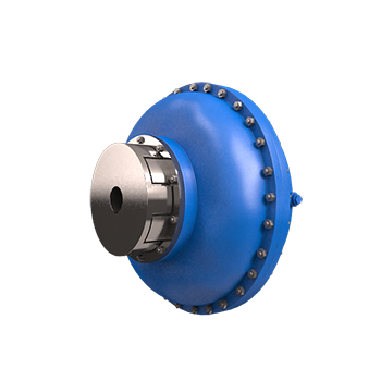
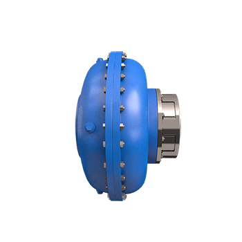
Type WF are steel-body constant-fill fluid couplings with a hollow-shaft execution on one end and a flexible coupling on the other for the respective shaft connections. They are available with a delayfil chamber as type WFDF and without delayfil as type WF.
A radially-displaceable execution is also offered, carrying a metallic-disc flexible coupling on both ends (WF HF / WFDX). These metallic-disc couplings need no lubrication and demand the least maintenance, while the weight of the coupling is shared between the motor and the driven machine — reducing the weight reaction on gearbox shafts, which are of small diameter in modern designs.
Key data
Engineered for demanding fluids.
Type WF HF couplings are radially displaceable, carrying a metallic-disc flexible coupling on both the input and output ends. Because the coupling weight is shared by the motor and driven machine shaft, the load reaction on slender gearbox shafts is minimised. The maximum torque-transmitting capacity is adjustable between 200% and 270% for type WF and 180% to 270% for WFDF.
Type WF couplings are suitable for operation with the following media:
- Water (aqua)
- Water–oil emulsion to HFB classification of the European Mines Safety Commission
- Mineral oil
All the benefits of a Fluidomat coupling
Type WF offers every advantage and performance characteristic of the aluminium-body Fluidomat fluid couplings.
- Virtually no-load start and run-up of the motor, with peak motor torque used for load acceleration
- Smooth, controlled acceleration of the driven machine
- Quick decay of the motor starting-current kick
- Adjustable starting characteristics and load limiting
- Dampening of shock loads, torsional fluctuations and vibrations
Rating table — WF water-filled couplings
Maximum ratings in KW at different input speeds (RPM). For final selection, please consult Fluidomat application engineering.
| WF model | 600 | 750 | 900 | 1000 | 1200 | 1500 | 1800 |
|---|---|---|---|---|---|---|---|
| WF 4 | 1 | 1.8 | 3 | 4 | 8 | 15 | 22 |
| WF 360 | 2.6 | 5 | 9 | 12 | 20 | 40 | 60 |
| WF 5 | 4 | 7.5 | 13 | 18 | 31 | 60 | 80 |
| WF 6 | 5.6 | 11 | 19 | 26 | 45 | 80 | 114 |
| WF 7 | 10 | 19 | 33 | 45 | 78 | 152 | 197 |
| WF 8 | 14.4 | 28 | 48 | 66 | 115 | 224 | 290 |
| WF 566 | 20 | 40 | 68 | 93 | 161 | 315 | 375 |
| WF 9 | 33 | 64 | 111 | 152 | 262 | 373 | 500 |
| WF 662 | 43 | 83 | 143 | 196 | 340 | 660 | 750 |
Maximum ratings in KW at the stated input speed (RPM). Ratings apply to the WF, WFDF and WFDX executions. Full dimension tables and flexible-coupling references are given below.
Technical specification & dimensions
Overall and mounting dimensions (mm), thread size and connected flexible-coupling references for the WF and WF HF ranges, as published by Fluidomat.
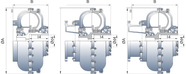
Dimensions — WF & WFDF / WFDX
Overall dimensions (mm), maximum bore, thread size and connected flexible-coupling model by coupling type.
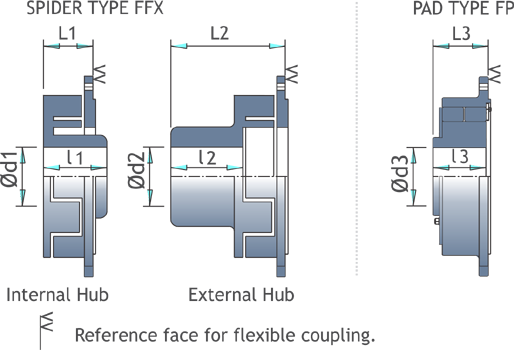
| Model | ØA | B | Ød4 max | ℓ4 | Threads ‘M’ BSW | Flexible coupling |
|---|---|---|---|---|---|---|
| WF-4 | 375 | 154 | 42 | 74 | 1" | FFX-1 |
| WF-360 | 418 | 220 | 55 | 112 | 1" | FFX-3 |
| WFDF-360 | 418 | 315 | 55 | 112 | 1" | FFX-3 |
| WF-5 | 470 | 250 | 80 | 135 | 1" | FFX-3 |
| WFDF-5 | 470 | 320 | 80 | 135 | 1" | FFX-3 |
| WF-6 | 512 | 253 | 85 | 140 | 1½" | FFX-4 |
| WFDF-6 | 512 | 328 | 85 | 140 | 1½" | FFX-4 |
| WFDX-6 | 512 | 373 | 85 | 140 | 1½" | FFX-4 |
| WF-7 | 570 | 277 | 95 | 155 | 1½" | FFX-4 |
| WFDF-7 | 570 | 355 | 95 | 155 | 1½" | FFX-4 |
| WFDX-7 | 570 | 377 | 95 | 155 | 1½" | FFX-4 |
| WF-8 | 620 | 291 | 95 | 170 | 1½" | FP-1/FFX-5 |
| WFDF-8 | 620 | 370 | 95 | 170 | 1½" | FP-1/FFX-5 |
| WFDX-8 | 620 | 451 | 95 | 170 | 1½" | FP-1/FFX-5 |
| WF-566 | 644 | 313 | 110 | 172 | 1½" | FP-1/FFX-5 |
| WFDF-566 | 644 | 392 | 110 | 172 | 1½" | FP-1/FFX-5 |
| WFDX-566 | 644 | 473 | 110 | 172 | 1½" | FP-1/FFX-5 |
| WF-9 | 715 | 367 | 110 | 200 | Ø50-8P* | FP-2A |
| WFDF-9 | 715 | 425 | 110 | 200 | Ø50-8P* | FP-2A |
| WFDX-9 | 715 | 508 | 110 | 200 | Ø50-8P* | FP-2A |
| WF-662 | 760 | 389 | 120 | 240 | Ø50-8P* | FP-2A |
| WFDF-662 | 760 | 482 | 120 | 240 | Ø50-8P* | FP-2A |
| WFDX-662 | 760 | 530 | 120 | 240 | Ø50-8P* | FP-2A |
All dimensions in mm. ØA outer diameter, B overall length, Ød4 max maximum bore, ℓ4 bore length. * denotes square thread.
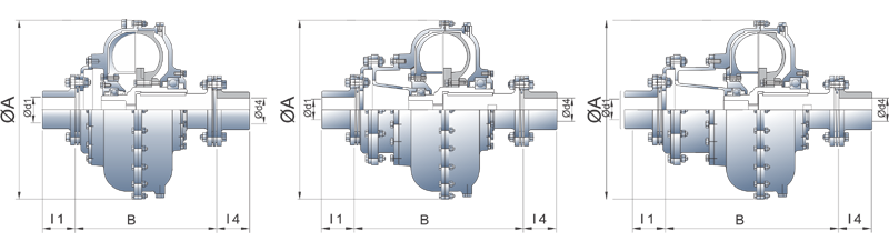
Dimensions — WF HF
Radially-displaceable execution with metallic-disc flexible couplings on both ends (WFHF / WFHFD / WFHFDX). Overall dimensions (mm) and connected flexible-coupling model by coupling type.
| Model | ØA | B | Ød1 max | ℓ1 | Ød4 max | ℓ4 | Flex coupling FXC |
|---|---|---|---|---|---|---|---|
| WFHF-4 | 380 | 278 | 55 | 70 | 55 | 70 | FXC-II |
| WFHFD-4 | 380 | 364 | 55 | 70 | 55 | 70 | FXC-II |
| WFHF-360 | 418 | 350 | 75 | 95 | 75 | 95 | FXC-IIIA |
| WFHFD-360 | 418 | 446 | 75 | 95 | 75 | 95 | FXC-IIIA |
| WFHF-5 | 470 | 378 | 75 | 95 | 75 | 95 | FXC-IIIA |
| WFHFD-5 | 470 | 465 | 75 | 95 | 75 | 95 | FXC-IIIA |
| WFHF-6 | 512 | 384 | 95 | 110 | 95 | 110 | FXC-III |
| WFHFD-6 | 512 | 458 | 95 | 110 | 95 | 110 | FXC-III |
| WFHFDX-6 | 512 | 504 | 95 | 110 | 95 | 110 | FXC-III |
| WFHF-7 | 570 | 402 | 95 | 110 | 95 | 110 | FXC-III |
| WFHFD-7 | 570 | 480 | 95 | 110 | 95 | 110 | FXC-III |
| WFHFDX-7 | 570 | 502 | 95 | 110 | 95 | 110 | FXC-III |
| WFHF-8 | 620 | 470 | 120 | 125 | 120 | 125 | FXC-IVA |
| WFHFD-8 | 620 | 550 | 120 | 125 | 120 | 125 | FXC-IVA |
| WFHFDX-8 | 620 | 630 | 120 | 125 | 120 | 125 | FXC-IVA |
| WFHF-566 | 644 | 500 | 120 | 125 | 120 | 125 | FXC-IVA |
| WFHFD-566 | 644 | 578 | 120 | 125 | 120 | 125 | FXC-IVA |
| WFHFDX-566 | 644 | 659 | 120 | 125 | 120 | 125 | FXC-IVA |
| WFHF-9 | 715 | 528 | 120 | 125 | 120 | 125 | FXC-IVA |
| WFHFD-9 | 715 | 586 | 120 | 125 | 120 | 125 | FXC-IVA |
| WFHFDX-9 | 715 | 669 | 120 | 125 | 120 | 125 | FXC-IVA |
| WFHF-662 | 760 | 604 | 150 | 200 | 150 | 200 | FXC-V |
| WFHFDF-662 | 760 | 689 | 150 | 200 | 150 | 200 | FXC-V |
| WFHFDX-662 | 760 | 745 | 150 | 200 | 150 | 200 | FXC-V |
All dimensions in mm. ØA outer diameter, B overall length, Ød1/Ød4 max maximum bore at each end, ℓ1/ℓ4 bore length. FXC = connected metallic-disc flexible-coupling model.
Diagrams & views
Proven across rotating equipment
Need a water-filled coupling for your drive?
Send us your motor rating, speed and driven-machine details and we’ll recommend the right WF, WFDF or WFDX model.